
Access Control Magnetic Door Lock Wiring Diagram
Access control systems have fundamentally transformed the way we secure environments, granting privilege and oversight to those who require it while simultaneously thwarting unauthorized access. At the heart of such systems lies an often overlooked yet indispensable component: the magnetic door lock. Understanding a wiring diagram for these locks not only illuminates the mechanistic intricacies involved but also underscores the critical role they play in modern security infrastructures. Such knowledge is crucial, especially for security professionals, contractors, and DIY enthusiasts looking to bolster safety at residential or commercial establishments.
The essence of an access control magnetic door lock is embedded in its operation. Rather than relying on traditional locking mechanisms, which can be susceptible to picking or forced entry, magnetic locks employ the principle of electromagnetism. When energized, an electromagnet generates a force strong enough to secure a door, providing a seamless yet formidable security solution. It is this simple, yet powerful, principle that becomes the foundation for a myriad of applications.
Before delving into the specificities of the wiring diagram, it is prudent to understand a few essential components associated with magnetic locks. The magnetic lock typically consists of an electromagnet—mounted on the door frame—and an armature plate attached to the door itself. Together, they form a closed circuit when the device is powered, compelling the armature to adhere firmly to the magnet. When the power supply is cut, the adhesive force is neutralized, allowing the door to open freely.
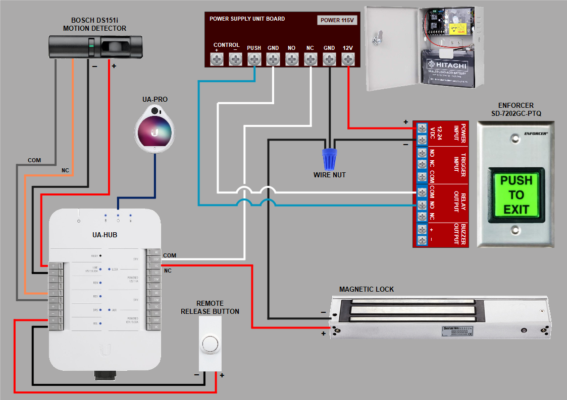
The wiring diagram for an access control magnetic door lock provides critical insights into how these components interrelate within the system. At a glance, the diagram typically features symbols representing essential elements such as power supplies, control panels, and various sensors. Among the most commonly utilized components in such a diagram include:
- Power Supply: The heart of the system, providing the necessary voltage (often 12 or 24 volts) to energize the magnetic lock.
- Control Panel: The brain of the operation, relaying commands to open or secure the lock based on user inputs, often linked to keypads, cards, or biometric scanners.
- Exit Button: A simple yet effective mechanism that permits individuals to exit without requiring a card or code.
- Door Position Switch: A safety feature that monitors the status of the door, ensuring that it remains secure when closed.
- Backup Battery: Offers continuous power in the event of an electrical failure, ensuring unwavering security.
When wiring these components, it is vital to adhere to certain protocols to ensure functionality and safety. The magnetic lock generally requires a constant power supply, typically activated via the control panel. A fuse might be integrated into this setup to protect against potential surges in electrical current, thereby safeguarding sensitive components from damage.
To illustrate, consider a straightforward wiring setup. The power supply connects to the magnetic lock directly and is also linked to the control panel. Upon receiving input from the access terminal (like a keypad), the control panel activates the power supply, thus energizing the lock. Conversely, when the exit button is pressed, a command is sent to the control panel, which in turn sends a signal to deactivate the lock for a set duration, permitting egress.
The wiring diagram becomes even richer when incorporating additional elements. For instance, one may integrate a door sensor to cease power to the magnet when the door is ajar, preventing potential accidents and enhancing safety compliance. Additionally, the installation of a delay timer can allow for brief exits without necessitating a reset of the entire system, adding an extra layer of convenience for high-traffic areas.
Considerations for installation are as paramount as the wiring itself. The location of the magnetic lock is vital; it should be installed in a manner that avoids susceptibility to tampering. Moreover, proper alignment of the armature plate is crucial, as any misalignment can result in ineffective locking or undue wear on components. Regular maintenance checks, such as ensuring the integrity of connections and cleanliness of surfaces, also contribute to the longevity and reliability of the access control system.
Moreover, awareness of local codes and regulations regarding electrical installations is essential, as non-compliance can lead to penalties or invalidation of warranties. It is advisable to consult with a licensed electrician or security specialist when navigating complex installations, particularly in commercial settings where liability and adherence to safety standards take precedence.
In conclusion, the underpinnings of an access control magnetic door lock present a fascinating study of security technology. A thorough understanding of the wiring diagram enriches our grasp of its operational narrative, revealing the synchrony between various components. This knowledge is not merely about understanding the wiring but embodies a commitment to safety, precision, and peace of mind. As we navigate an era increasingly defined by security concerns, such insights serve both the practitioner and the layperson, illustrating that the strength of any lock is only as formidable as the knowledge and expertise of those who install and maintain it.
If you are looking for Door Access Control 280kg Electric Lock RFID Keypad Entry 12V Power Kit you’ve came to the right web. We have 10 Images about Door Access Control 280kg Electric Lock RFID Keypad Entry 12V Power Kit like Magnetic Door Lock Schematic Diagram - Wiring Draw And Schematic, Magnetic Door Lock Schematic Diagram » Wiring Draw And Schematic and also Magnetic Door Lock Schematic Diagram » Wiring Draw And Schematic. Here it is:
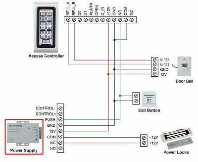
Door Access Control 280kg Electric Lock RFID Keypad Entry 12V Power Kit
 www.wiringdraw.com### Magnetic Door Lock Schematic Diagram - Wiring Draw And Schematic

 toplocksecurity.com### Wiring Diagram For Magnetic Door Lock|TOPLOCK
 toplocksecurity.com### Access Control Magnetic Door Lock Wiring Diagram
 schematicvizier.z19.web.core.windows.net### Magnetic Door Lock Wiring Diagram - Search Best 4K Wallpapers
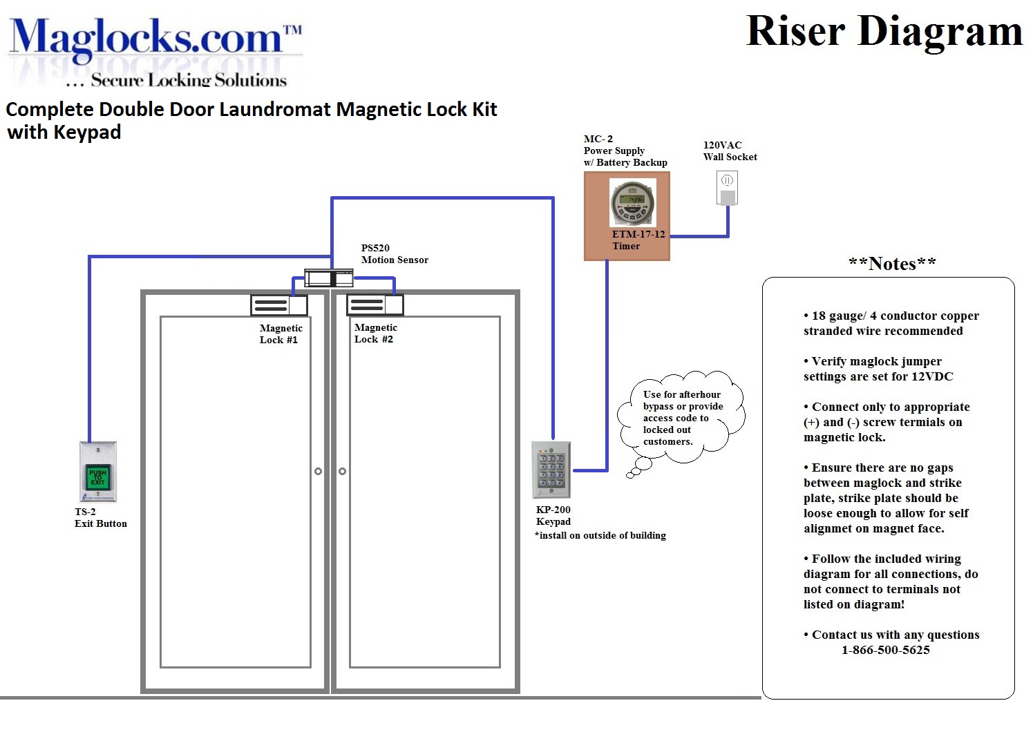 www.smarts4k.comwiring maglock control kit laundromat keypad doors magnets
Wiring Diagram For Magnetic Door Lock|TOPLOCK
 toplocksecurity.com### Door Access Control 280kg Electric Lock RFID Keypad Entry 12V Power Kit
 rowher.saisonsdumonde.fr### Wiring Diagram For Magnetic Door Lock|TOPLOCK
 toplocksecurity.com