
Brushless Motor Controller Circuit Diagram
In the world of modern electronics, the brushless motor controller circuit diagram holds paramount significance. It is a depiction that not only outlines the interconnections within the circuit but also encapsulates the operational prowess of brushless motors. As technology progresses, understanding this intricate circuit becomes essential for engineers and hobbyists alike.
The brushless motor, unlike its brushed counterpart, operates without brushes, thus eliminating the need for mechanical contacts and enhancing efficiency. Consequently, brushless motors have garnered extensive applications in robotics, drones, and electric vehicles, necessitating sophisticated control mechanisms. Central to these mechanisms is the brushless motor controller, which facilitates precise speed control, torque regulation, and directional maneuverability.
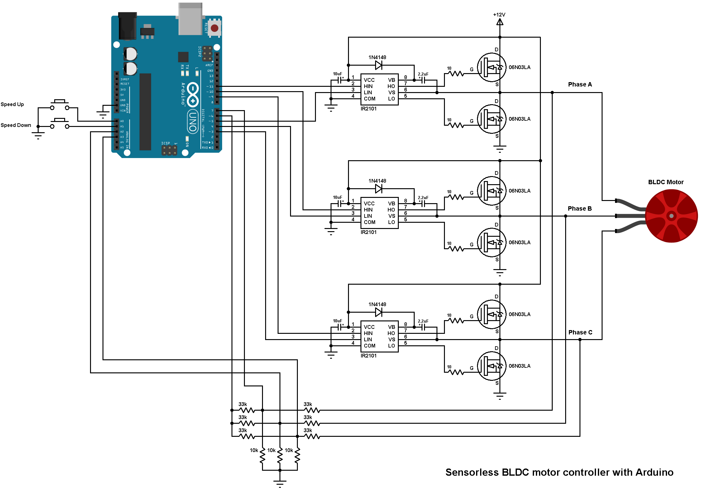
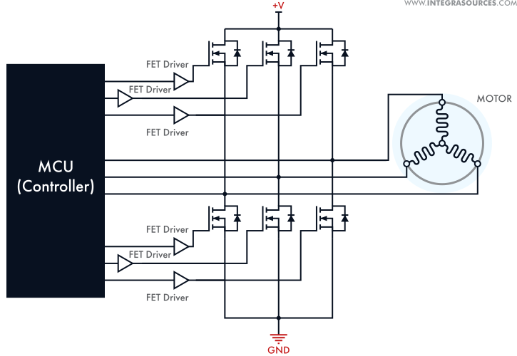
The circuit diagram of a brushless motor controller is a roadmap. It delineates the functional blocks that contribute to the overall operation of the motor. Typically, this diagram showcases the essential components: a microcontroller, power transistors, a feedback system, and various electronic sensors. Each component plays a vital role in ensuring the smooth operation of the motor.
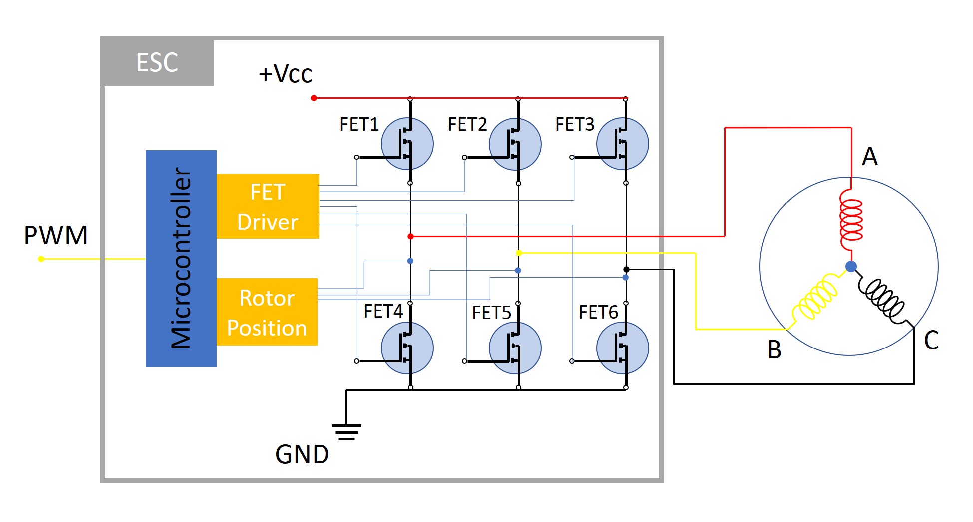
Microcontroller: At the heart of the brushless motor controller is the microcontroller, acting as the brain and orchestrating the entire system. This component processes input signals from sensors and generates appropriate output signals to the power transistors. It implements algorithms that optimize performance, such as field-oriented control, ensuring efficient operation across various speeds and loads.
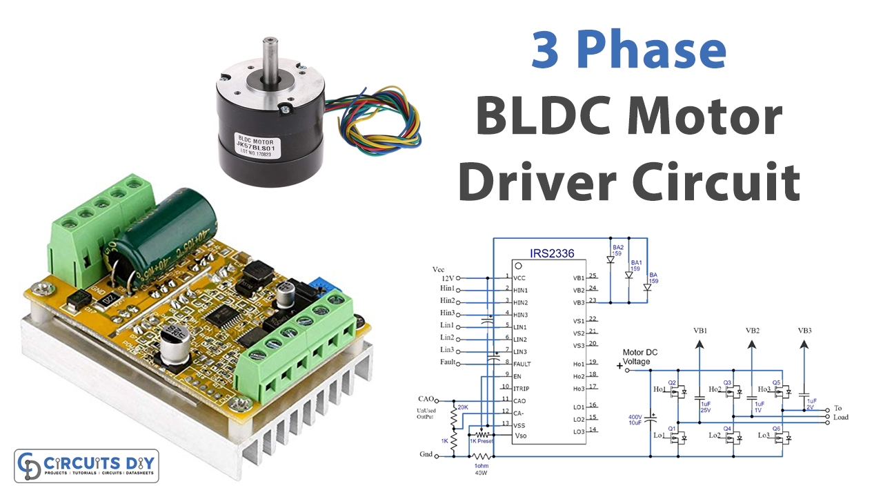
Power Transistors: The power transistors, often MOSFETs or IGBTs, are crucial for switching the current to the motor phases. By rapidly turning on and off, these transistors create the electrical waveforms necessary to drive the brushless motor. The selection of power transistors is critical; characteristics such as voltage rating and switching speed must align with the application’s requirements to prevent overheating and ensure reliability.
Feedback Mechanisms: A robust feedback system is integral to a brushless motor controller. This system may include encoders or Hall effect sensors that provide real-time position and speed data. The microcontroller utilizes this feedback to adjust the voltage and current supplied to the motor, thereby maintaining optimal performance under varying conditions. Without this continuous feedback loop, maintaining accuracy and efficiency would be nearly impossible.
Schematic Representation: When examining a typical brushless motor controller circuit diagram, one might notice several distinct sections. The power input section is where the energy source connects, often showcasing capacitors that mitigate voltage spikes. Following this is the driver section, which energizes the transistors. The microcontroller component interfaces seamlessly, highlighting data highways that connect to various sensors.
The relationships among components can be fascinating. For instance, capacitors not only serve as noise filters but also stabilize voltage, ensuring a clean supply to the motor drivers. Understanding these connections aids in troubleshooting and optimizing designs. A well-designed circuit can lead to greater reliability and longevity of the motor system as a whole.
Application Domains: The advantages of brushless motors and their controllers have paved the way for their incorporation into diverse fields. In the aerospace industry, drones utilize brushless motors for their superior power-to-weight ratio. Each flight controller employs a sophisticated brushless motor controller circuit to achieve responsive and agile maneuverability.
In electric vehicles, increased efficiency translates directly to extended range and battery life. Engineers meticulously design brushless motor controllers to manage high currents while mitigating energy losses. The automotive market is rapidly evolving, and the brushless motor controller is a critical enabler of this transformation.
Future Trends: As technology advances, the future of brushless motor controller designs will likely embrace digital control methods. High-level programming languages and artificial intelligence will foster improvements in adaptability and efficiency. Thus, designers should keep abreast of emerging technologies to harness the full potential of brushless motors.
The development of integrated circuits that combine microcontrollers with power drivers can significantly reduce the size and complexity of brushless motor controllers. Such advancements can streamline designs, opening opportunities for miniaturization in applications where space is a premium.
Moreover, with the rise of the Internet of Things (IoT) and smart technology, interfacing brushless motor controllers with cloud services could enable predictive maintenance, optimizing performance in real-time. Such innovations exemplify the ongoing evolution of brushless motor technology.
In summation, comprehending the intricacies of the brushless motor controller circuit diagram is essential for any engineering enthusiast or professional. This diagram is a vital tool that encapsulates the synthesis of innovation and design. By understanding the roles of various components and their interactions, one can harness the full capabilities of brushless motors, paving the way for future innovations in various fields. The journey from mere schematic to operational excellence is a testament to the sophistication inherent in brushless motor technology, and exploring this fascinating domain continues to unveil new horizons in engineering.
If you are searching about Brushless Controller 2 Mode you’ve came to the right place. We have 10 Images about Brushless Controller 2 Mode like Brushless BLDC Motor ESC circuit | Electronics projects diy, Electronic, Brushless Controller 2 Mode and also Brushless Motor Driver Circuit. Here you go:
Brushless Controller 2 Mode
 circuitdiagramgosse.z4.web.core.windows.net### Brushless Motor Driver Circuit
 florjanll1guidediagram.z14.web.core.windows.net### Homemade Esc Circuit Diagram For Brushless Motor “brushles
 circuitlogyerorpqsd.z21.web.core.windows.net### Brushless Dc Motor Circuit Diagram Brushless Bldc Inverter W
 slavinne6cuschematic.z14.web.core.windows.net### Brushless BLDC Motor ESC Circuit | Electronics Projects Diy, Electronic
 www.pinterest.com### Speed Controller Esc Circuit Diagram For Brushless Motor Sim
 diagramjugohromu6xe.z14.web.core.windows.net### Brushless Dc Motor Controller Circuit
 diagramdrexenropb4.z19.web.core.windows.net### Speed Controller Esc Circuit Diagram For Brushless Motor Sim
 diagramtorrasa1cz.z21.web.core.windows.net### Brushless Synchronous Motor Circuit Diagram Synchronous Indu
 ddoniauklywiring.z21.web.core.windows.net### Brushless Motor Circuit Diagram Brushless Dc Motor (bldc)
 circuitchalcosissmw.z21.web.core.windows.net