
Common Cathode 7 Segment Display Pin Configuration
Imagine yourself as a modern-day inventor. You’re brimming with enthusiasm, armed with an array of electronic components, yet you find yourself stymied by a seemingly innocuous device: the common cathode 7-segment display. This ubiquitous electronic element graces everything from digital clocks to electronic meters. Your challenge, should you choose to accept it, is to unlock the enigma of its pin configuration and harness its potential in your upcoming project. Are you ready? Let’s illuminate the path!
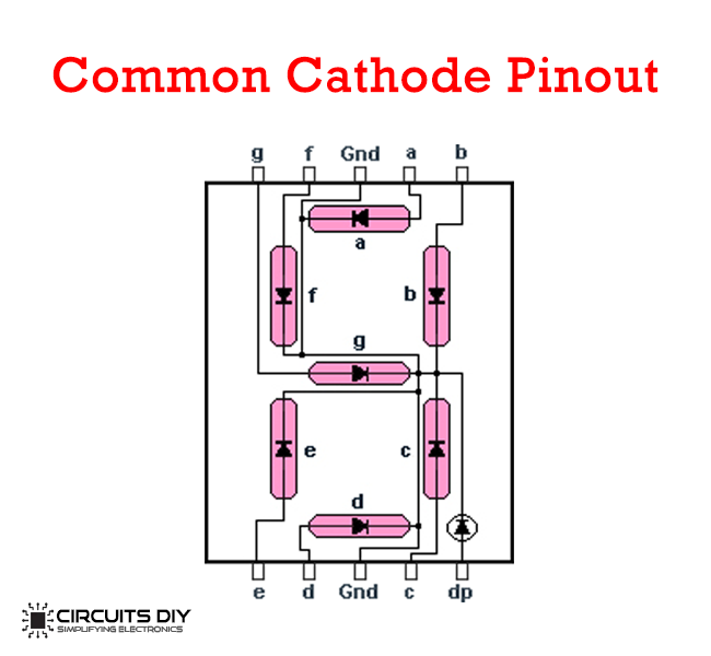
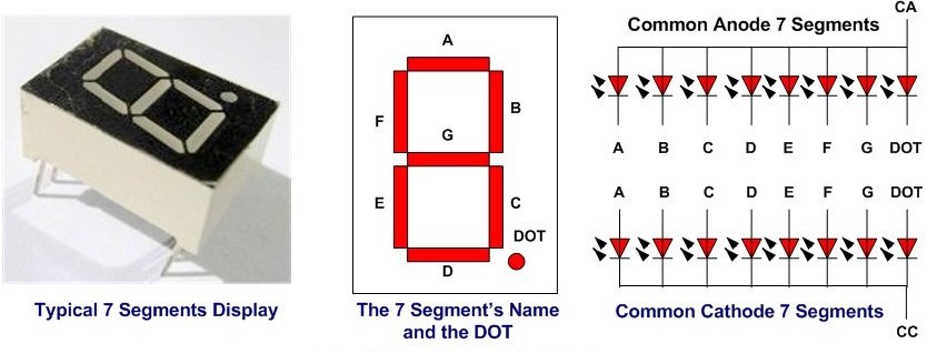
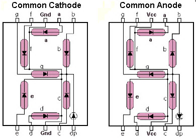
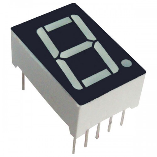
At its core, the common cathode 7-segment display is a simple yet effective visual device designed to convey numerical information through a series of illuminated segments. Each display consists of seven individual segments labeled from A to G, along with an additional segment for the decimal point. The term “common cathode” signifies that all the cathodes of the individual segments are connected together to the ground. When you apply a positive voltage to the appropriate pins, the corresponding segments illuminate, creating the numbers you wish to display. Understanding its pin configuration is crucial to proficiently using this component in your electronic circuits.
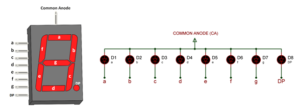
Before we delve into the intricate specifics of the pinout, let’s identify the key segments of the display. The digits typically displayed range from 0 to 9, each manifested by illuminating various combinations of these segments. Here’s a breakdown of the segment designations:
- A: Top Horizontal Segment
- B: Upper Right Vertical Segment
- C: Lower Right Vertical Segment
- D: Bottom Horizontal Segment
- E: Lower Left Vertical Segment
- F: Upper Left Vertical Segment
- G: Middle Horizontal Segment
- DP: Decimal Point
Now, onto the pin configuration itself. The pin layout is paramount for your circuit design. A standard common cathode display typically has a total of 10 pins. Although the exact pinout may vary among manufacturers, the general configuration remains consistent. Below is a common representation:
    Pin 1: E (Lower Left Segment)
    Pin 2: D (Bottom Segment)
    Pin 3: C (Lower Right Segment)
    Pin 4: DP (Decimal Point)
    Pin 5: A (Top Segment)
    Pin 6: F (Upper Left Segment)
    Pin 7: G (Middle Segment)
    Pin 8: B (Upper Right Segment)
    Pin 9: Common Cathode (Ground)
    Pin 10: (Not Used)
Take note that connections must be made meticulously, ensuring that power is supplied correctly to avoid catastrophic misfires in your project’s functionality. An important aspect of utilizing this display is understanding that in a common cathode configuration, the power supply connects to the anodes of the segments while the cathodes are collectively grounded.
Visual aids can greatly enhance comprehension. It is often beneficial to reference diagrams, such as the one depicted in the following link: Common Cathode 7 Segment Display Pinout. Such resources can serve as a handy reference to bolster your understanding and facilitate the assembly of your circuits.
Equipped with knowledge of the pin configuration, you can venture into the myriad applications of the common cathode 7-segment display. For example, driving the display using a microcontroller, such as an Arduino, opens a plethora of creative possibilities. With only a few additional resistors and minimal wiring, you can programmatically control the digits displayed based on inputs or sensor data.
The integration process is relatively straightforward. Connect each pin of the display to your processing unit, implementing current-limiting resistors where necessary. A typical value for these resistors usually ranges between 220Ω and 1kΩ, depending on the desired brightness and the operating voltage. The microcontroller serves as your control hub, dictating which segments to illuminate through binary control, thereby displaying the desired numerals.
The significance of this component in the realm of electronics cannot be overstated. Common cathode displays simplify numerical representation, making them fantastic tools for prototyping and developing various electronic devices. Whether it’s for creating a digital scoreboard, a calculator, or an electronic thermostat, understanding this pin configuration will bolster your electronic craftsmanship.
In summation, your challenge has been laid before you. The common cathode 7-segment display offers endless potential when wielded with precision and understanding. As you embark on your electronics journey, remember to refer back to the foundational knowledge of the display’s pin configuration and the behaviors of its segments. Soon, you’ll be illuminating the path towards innovation, one segment at a time.
If you are searching about Common Cathode 7 Segment Display Pinout you’ve visit to the right web. We have 10 Images about Common Cathode 7 Segment Display Pinout like Common cathode 7 segment display pin diagram - milonutri, Common cathode 7 segment display pin diagram - batmanring and also Common cathode 7 segment display pin diagram - batmanring. Read more:
Common Cathode 7 Segment Display Pinout
 mungfali.com### Common Cathode 7 Segment Display Pinout
 mungfali.com### Common Cathode 7 Segment Display Pinout
 mungfali.com### Common Cathode 7 Segment Display Pinout
 mungfali.com### Common Cathode 7 Segment Display Pin Diagram
 schematictowplanes.z5.web.core.windows.net### Common Cathode 7 Segment Display Pinout
 mungfali.com### 7 Segment Display - Common Cathode
 www.tu-eshop.comdisplay cathode common segment
Common Cathode 7 Segment Display Pin Diagram - Milonutri
 milonutri.weebly.com### Common Cathode 7 Segment Display Pin Diagram - Batmanring
 batmanring.weebly.com### 7-Segment Display Connection (Common Anode & Common Cathode
