
Step Down Transformer Wiring Diagram
In the realm of electrical engineering, the step-down transformer emerges as an essential device, adept at converting high voltage electricity to a lower voltage suitable for various applications. Understanding the wiring diagram of a step-down transformer not only aids in the comprehension of its operational capacity but also provides invaluable insights into its workings and the intricate nature of electrical circuits. This article delves into the wiring diagram of a step-down transformer, shedding light on the fundamental components and their interconnections. With the aid of a detailed schematic, we will explore its significance and multiple applications in contemporary settings.
The step-down transformer primarily operates on the principles of electromagnetic induction, effectively changing voltage levels while maintaining frequency. In essence, it consists of primary and secondary windings, with the primary winding connected to the higher voltage power source and the secondary coil delivering the reduced voltage output. Understanding the wiring diagram reveals the intricate relationships between these components, allowing technicians and engineers to troubleshoot or design robust circuits.
To fully appreciate a step-down transformer’s wiring diagram, it is imperative to be familiar with several key terms:
- Primary Winding: The coil connected to the input voltage source, facilitating the creation of a magnetic field.
- Secondary Winding: The coil responsible for generating the output voltage, where the voltage is transformed to a lower level.
- Turns Ratio: The ratio between the number of turns in the primary winding compared to the secondary winding, which determines the voltage transformation.
- Core Material: The ferromagnetic material upon which the windings are wrapped, optimizing the magnetic link between primary and secondary coils.
- Insulation: The material that separates the windings and protects against electrical leakage.
- Tap Changer: A device used to adjust the voltage output by changing the connection point on the winding.
- Polarities: The orientation of the windings, crucial for ensuring the correct phase relationship between input and output voltages.
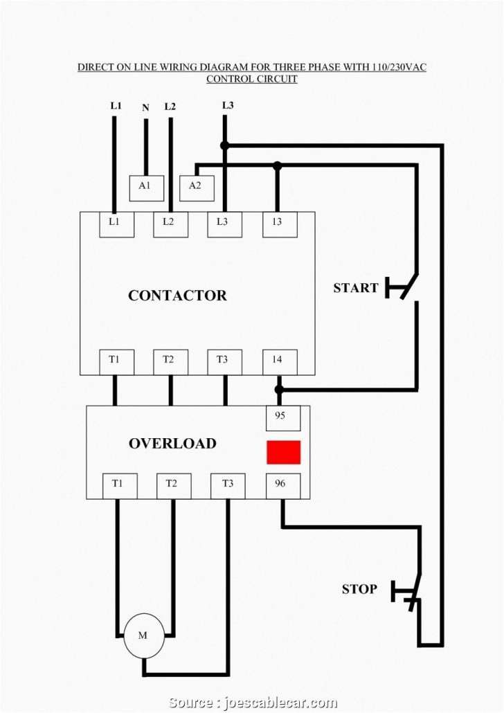
Now, let’s delve into the wiring diagram itself, which encapsulates the aforementioned elements through a visual representation. A typical step-down transformer wiring diagram will illustrate the primary and secondary windings, interconnected through the core. The insulation between the coils is pivotal in preventing short circuits and maintaining efficacy.
Moreover, a transformer can have a center-tapped secondary winding, allowing for multiple output voltage levels. In such configurations, tapping occurs at the midpoint of the secondary winding, and connections are drawn outward. This versatile arrangement supports various applications, including dual power supplies in electronic circuits.
The core material, a fundamental component of any transformer, is typically made from laminated silicon steel. This laminated construction minimizes eddy current losses, enhancing efficiency. The windings, made from insulated copper or aluminum wire, are tightly wound about the core, promoting an optimal magnetic field with minimal losses. According to the turns ratio, if the primary winding has twice the number of turns compared to the secondary winding, the output voltage will be half that of the input. For instance, a 240V primary input resulting in a 120V output showcases the practical utility of such devices in everyday applications.
In industrial settings, the applications of step-down transformers are boundless. They serve as integral components in power distribution networks, providing the necessary voltage reduction for consumption. Whether in substations feeding into residential neighborhoods or in factories powering heavy machinery, step-down transformers play a pivotal role in safeguarding electrical safety and efficiency. In domestic environments, they ensure that high-voltage electrical systems can effectively supply power to appliances without damaging sensitive components.
Furthermore, the wiring diagram also assists in elucidating the safety measures integral to transformer design. Overcurrent protection devices, such as fuses or circuit breakers, are often incorporated into the system. This safeguard prevents damage due to excessive current, ensuring that both the transformer and connected devices remain unharmed during irregular scenarios.
It is important to note that while wiring diagrams provide a blueprint for installation and troubleshooting, they also require a keen understanding of safety protocols. When working with step-down transformers, adherence to fundamental electrical safety practices is crucial. This includes de-energizing circuits before commencing work, utilizing appropriate personal protective equipment, and ensuring that all connections are secure to mitigate the risk of electrical faults.
In conclusion, the wiring diagram of a step-down transformer serves as a cardinal tool for both novice electricians and seasoned professionals. By providing a clear visual representation of the connections between components, it enhances comprehension of the device’s operation and facilitates practical implementations. As the world becomes increasingly reliant on electrical power, understanding these diagrams will remain of paramount importance in the ongoing advancement of electrical systems. The foundational knowledge gained from such studies will empower individuals to engage effectively with modern technology, ensuring that engineers, technicians, and hobbyists alike can navigate the intricate web of electrical engineering with confidence.
For a detailed visual reference, consider examining the following diagram:

If you are searching about Schematic Diagram Step Down Transformer - Circuit Diagram you’ve visit to the right place. We have 10 Images about Schematic Diagram Step Down Transformer - Circuit Diagram like Step Down Transformer Wiring Diagram | Manual E-Books - Transformer, Step Down Transformer Wiring Diagram | Manual E-Books - Transformer and also Wiring diagram for 3-phase step-down transformer. Here it is:
Schematic Diagram Step Down Transformer - Circuit Diagram
 www.circuitdiagram.co### Schematic Diagram Step Down Transformer - Circuit Diagram
 www.circuitdiagram.co### Step Down Transformer Wiring Diagram | Manual E-Books - Transformer
 2020cadillac.com### Wiring Diagram For 3-phase Step-down Transformer
 schempal.com### Abb Transformer Wiring Diagram
 diagramdamnaviyet.z21.web.core.windows.net### Step Down Transformer Wiring Diagram | Manual E-Books - Transformer
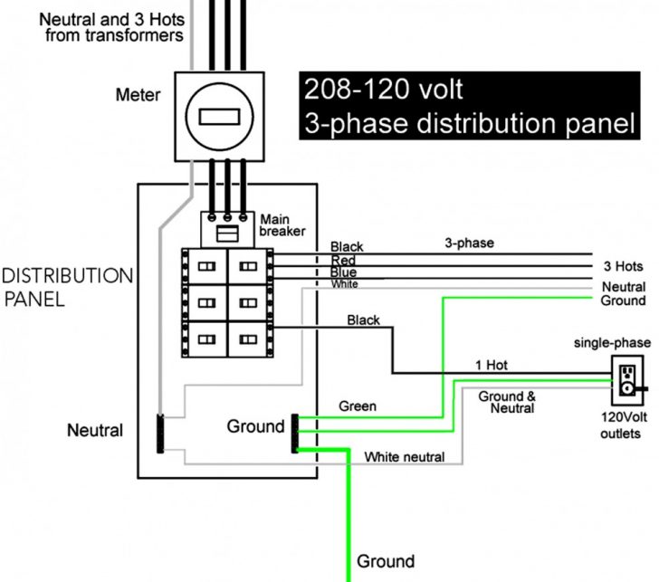 2020cadillac.comtransformer volt 277 480v 120v kva circuit volts 2020cadillac
Square D Step Down Transformer Wiring Diagram - Circuit Diagram
 www.circuitdiagram.co### Transformer Wiring Diagram Explained
 guidediagrambaleful.z21.web.core.windows.net### How To Read Transformer Wiring Diagram
 wiringdetention.z21.web.core.windows.net### Schematic Diagram Step Down Transformer - Circuit Diagram